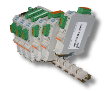
The use of the InRailBus offers the following advantages for CANopen® I/O modules of esd's CAN-CBX-IO series:
-
Different modules of the CAN-CBX-IO series can be strung together via the InRailBus.
-
Replacement of individual modules of the CAN-CBX-IO series from the InRailBus without interruption of CAN or supply voltage.
-
Convenient wiring suitable for control cabinets.
-
Automatic functional earth contact (FE).
ATTENTION
In general, for the CAN wiring all applicable rules and regulations (EU, DIN), e.g. regarding electromagnetic compatibility, security distances, cable cross-section or material, have to be observed.
Please also refer to our general CAN-Wiring Notes.
Current circuits which are connected to the device have to be sufficiently protected against hazardous voltage (SELV according to EN 60950-1). The CAN-CBX modules may only be driven by power supply current circuits, that are contact protected. A power supply, that provides a safety extra-low voltage (SELV) according to EN 60950-1, complies with these conditions.


Position the InRailBus connector on the mounting rail and snap it onto the mounting rail using slight pressure. By plugging the individual bus connectors together, the communication and power signals are contacted with each other (in parallel with one). The bus connectors can be connected as required before or after the CAN-CBX module is plugged on.

Now swivel the CAN-CBX module onto the mounting rail by moving the module downwards according to the direction of the arrow in figure Inserting a CAN-CBX module. The housing is mechanically guided by the guide bar of the bus connector.
When mounting the CAN-CBX module the metal foot catch snaps on the bottom edge of the mounting rail. The module is now firmly seated on the mounting rail and is connected to the InRailBus via the bus connector. If necessary, connect the bus connectors to each other and connect the +24 V supply voltage and the CAN interface to the InRailBus as described below.

Connection via the InRailBus
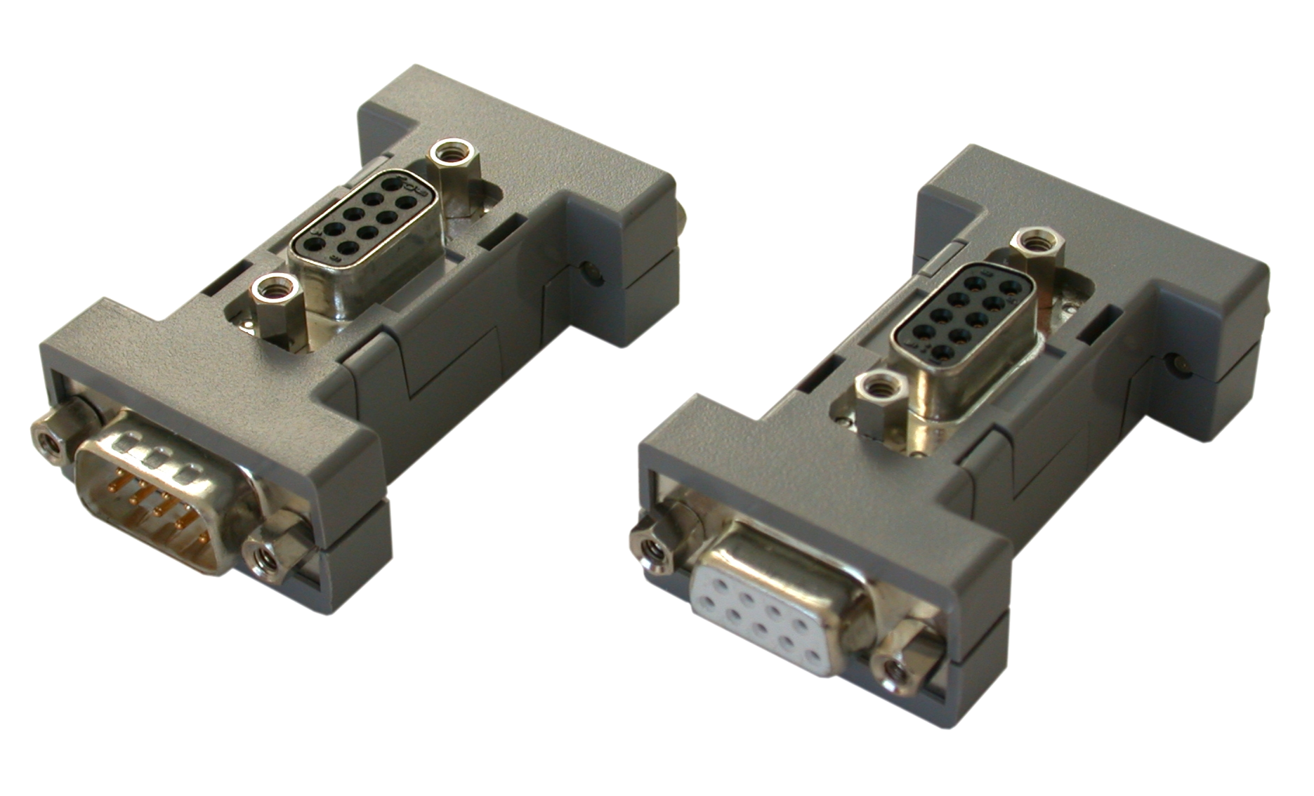
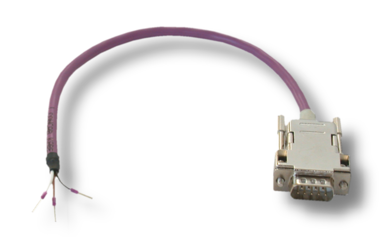
A terminal plug is needed to connect the supply voltage and the CAN signals via the InRailBus. The terminal plug is not included in the scope of delivery of the CBX-IO modules and must be ordered separately (order no.: C.3000.02).

Insert the terminal plug from the right into the socket side of the outer mounting rail bus connector of the InRailBus, as shown in Figure: Mounting rail with InRailBus connectors and terminal plug. Then connect the CAN interface and the supply voltage via the terminal plug as described below.
Connection of CAN

In general, the CAN signals can be fed in via the InRailBus or via the CAN connector of the first CAN-CBX module in the CAN-CBX station. The signals are then connected through the CAN-CBX station via the InRailBus.
The CAN signals may be lead through via the CAN connector of the CAN-CBX module mounted at the other end of the CBX station. However, the CAN signals must not be connected via the CAN connectors of the middle CAN-CBX modules of the CBX station, as this would lead to impermissible branching.
Please note that a bus terminating resistor must be connected to the CAN-CBX module located at the end of the InRailBus if the CAN bus ends there (see Figure CAN-CBX-Station with connection of CAN and CAN bus termination)
Connection of the Supply Voltage
The power supply can be connected either via the +24 V connector or via the InRailBus connector.


ATTENTION
The connections for the 24 V supply voltage are connected internally and must not be supplied by two independent power sources at the same time!
Earthing of the Mounting Rail
The module is connected to the mounting rail via its functional earth contact. This improves the stability against electromagnetic disturbances. The mounting rail must therefore be connected to a suitable functional earth contact in the environment or in the installation.
It must be ensured that the impedance of the connection is kept low.
The functional earth contact of the module does not ensure electrical safety.
Remove the CAN-CBX Module from InRailBus
If the CAN-CBX module is only connected via the InRailBus, proceed as follows when removing it:
Detach the module from the mounting rail by moving the foot catch (see Figure Mounted CAN-CBX module) downwards (e.g. with a screwdriver). In doing so, the module detaches from the bottom edge of the mounting rail and can be removed.