For the CAN wiring all applicable rules and regulations (EU, DIN), e.g. regarding electromagnetic compatibility, security distances, cable cross-section or material, have to be observed.
NOTICE
This page applies to CAN networks with bit rates up to 1 Mbit/s. If you work with higher bit rates, as for example used for CAN FD, the information given on this page must be examined for applicability in each individual case. For further information refer to the CiA® CAN FD guidelines and recommendations (https://www.can-cia.org/).
CAN Wiring Standards
Flexibility in the design of CAN networks is a major strength of the various extensions based on the CAN standard ISO11898-2, such as CANopen, ARINC825, DeviceNet and NMEA2000. However, taking advantage of this flexibility absolutely requires a network design that takes into account the interactions of all network parameters.
In some cases, the CAN organizations have adapted the scope of CAN in their specifications to enable applications outside the ISO 11898 standard. They have imposed system-level restrictions on data rate, line length and parasitic bus loads.
However, when designing CAN networks, a margin must always be planned for signal losses over the entire system and cabling, parasitic loads, network imbalances, potential differences against earth potential, and signal integrities. Therefore, the maximum achievable number of nodes, bus lengths and stub lengths may differ from the theoretically possible number!
esd has limited its recommendations for CAN wiring to the specifications of ISO 11898-2. A description of the special features of the derived specifications CANopen, ARINC825, DeviceNet and NMEA2000 is omitted here
Consistent compliance with the ISO 118998-2 specifications offers significant advantages:
- Reliable operation due to proven design specifications
- Minimization of error sources due to sufficient distance to the physical limits.
- Unproblematic maintenance, because there are no "special cases" to consider for future network modifications and troubleshooting.
Of course reliable networks can be designed according the specifications of CANopen, ARINC825, DeviceNet and NMEA2000, however it must be observed that it is strictly not recommended to mix the wiring guidelines of the various specifications!
Selecting Cables
NOTICE
esd grants the EU Conformity of a product, if the CAN wiring is carried out with the CAN cables that are required for this particular product.
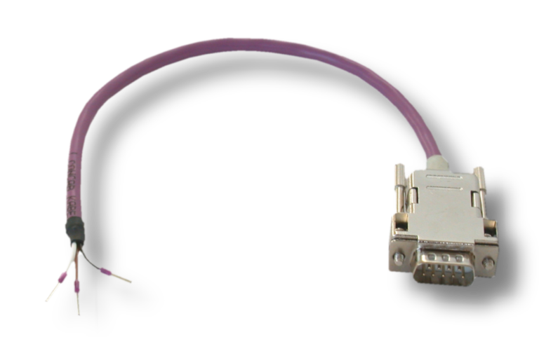
Depending on the product at least single shielded two-wire or four-wire twisted-pair cables must be used, that meet the requirements of ISO 118982-2 standard.
For information on whether the usage of two-wire or four-wire cables is required for a product, please refer to the manual of the respective product.
Please refer to the following wiring instructions for single-shielded two-wire twisted-pair cables and single-shielded four-wire twisted-pair cables.
Depending on the signal propagation times of the line, the achievable total line length of a CAN network increases with a decreasing bit rate (see bus length).
General Rules for correct Wiring
The following basic rules for CAN bus wiring with single-shielded two-wire or four-wire twisted-pair cables should be strictly observed::
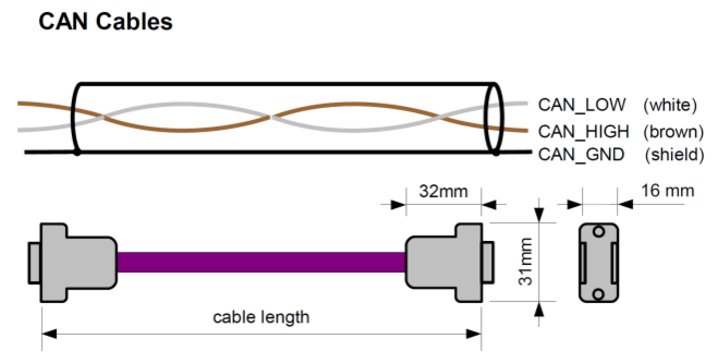
- A suitable cable type with a wave impedance of approx. 120 Ω ±10% and an adequate conductor cross-section (≥ 0.22 mm²) must be used. The voltage drop over the wire must be taken into account.
- Selection of the suitable cable depending on the environment.
- For usage in light industrial environment use at least a two-wire CAN cable whose wires are to be assigned as follows:
- Two twisted wires are to be assigned with the CAN signal lines (CAN_H, CAN_L).
- The cable shield must be connected with the reference potential (CAN_GND).
- For usage in heavy industrial environment use a four-wire CAN cable whose cores are to be assigned as follows:
- Two twisted wires are to be assigned with the CAN signal lines (CAN_H, CAN_L).
- The other two twisted wires are to be assigned to the reference potential (CAN_GND).
- The cable shield must be connected to functional earth (FE) at least at one point.
- For usage in light industrial environment use at least a two-wire CAN cable whose wires are to be assigned as follows:
- The reference potential CAN_GND has to be connected to functional earth (FE) at exactly one point.
- A CAN bus line must not branch (exception: short cable stubs) and must be terminated with the characteristic impedance of the line (generally 120 Ω ±10%) at both ends (between the signals CAN_L and CAN_H and not to CAN_GND).
- Keep cable stubs as short as possible (l < 0.3 m).
- Select a working combination of bit rate and cable length.
- Keep cables away from disturbing sources. If this cannot be avoided, double shielded wires are recommended.
Light industrial Environment (single twisted Pair Cable)
CAN Wiring for light industrial Environment
")
Cabling in light industrial Environment
To connect CAN devices with just one CAN connector per net use a short stub (< 0.3 m) and a T-connector (available as accessory). If this devices are located at the end of the CAN network, the CAN terminator “CAN-Termination-DSUB9” can be used.

")

Branching
- In principle, the CAN bus has to be realized in a line. The nodes are connected to the main CAN bus line via short cable stubs. This is usually realised by so called T-connectors.
- If a mixed application of single twisted and double twisted cables can not be avoided, ensure that the CAN_GND line is not interrupted!
- Deviations from the bus structure can be realized by using Repeaters.
Heavy industrial Environment: When using esd's CAN-T-Connector (order no.: C.1311.03) in heavy industrial environment and with four-wire twisted cables, it must be noted that the shield potential of the conductive DSUB housing is not looped through this type of T-connector. This interrupts the shielding. Therefore you have to take appropriate measures to connect the shield potentials as described in the T-Connector manual. For further information, please refer to the CAN-T-Connector manual (order no.: C.1311.21).
Alternatively, a T-connector can be used, in which the shield potential is looped through, e.g. the DSUB9 connector from ERNI (ERBIC CAN BUS MAX, order no.:154039).

Termination Resistor
- A termination resistor must be connected at both ends of the CAN bus.
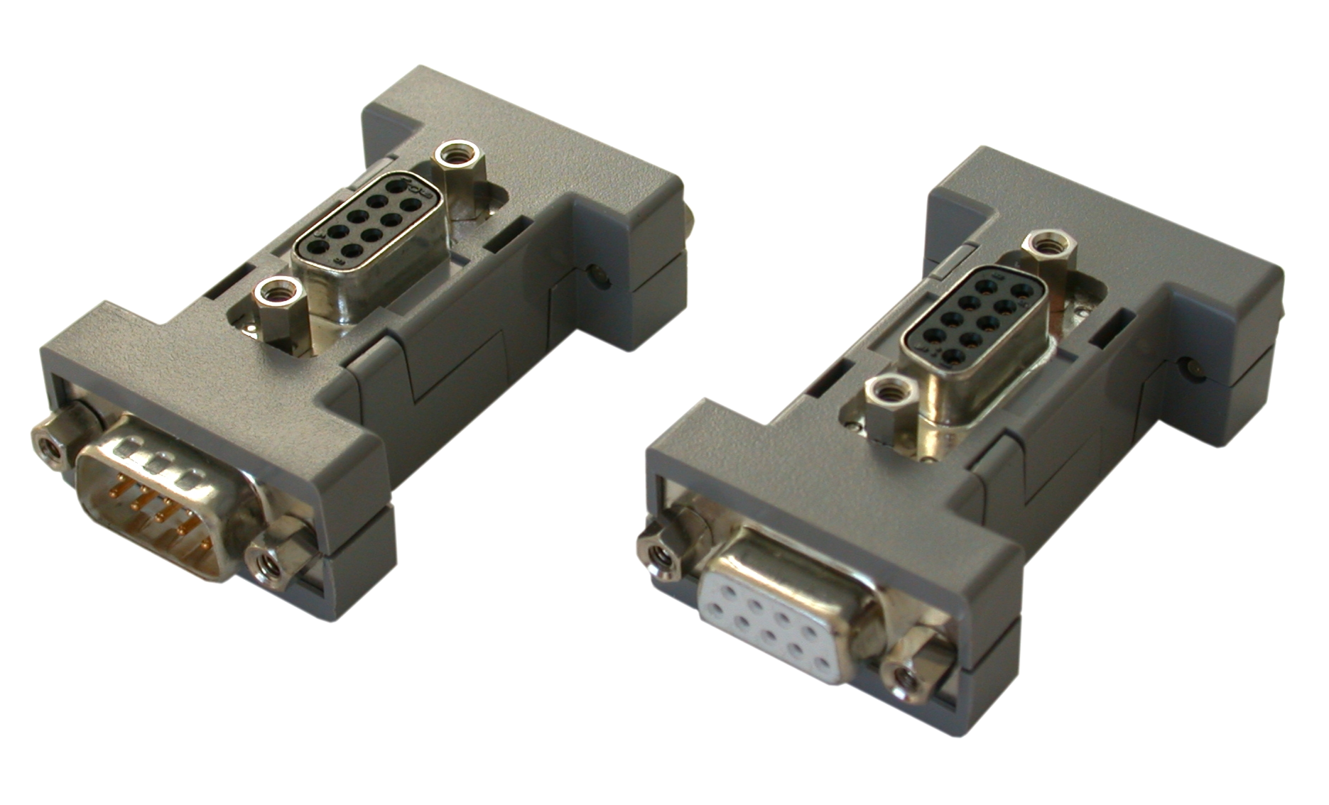
If an integrated CAN termination resistor is connected to the CAN interface at the end of the CAN bus, this integrated termination must be used instead of an external CAN termination resistor. - 9-pole DSUB-termination connectors with integrated termination resistor and plug contacts and socket contacts are available from esd under order no. C.1303.01.
- For termination of the CAN bus and grounding of the CAN_GND, DSUB terminators with pin contacts (C.1302.01) or socket contacts (C.1301.01) with additional functional earth contact are available (light industrial environment). As accessories we offer CAN cables, T-connectors and terminating resistors plugs.
Heavy industrial Environment: 9-pole DSUB-connectors with integrated switchable termination resistor can be ordered e.g. from ERNI (ERBIC CAN BUS MAX, socket contacts, order no.:154039).
Electrical Grounding of the CAN Network
- For CAN devices with electrical isolation the CAN_GND must be connected between the CAN devices.
- CAN_GND should be connected to the earth potential (FE) at exactly one point in the network
- Each CAN interface with electrical connection to earth potential acts as a grounding point. For this reason, it is recommended not to connect more than one CAN device with electrical connection to earth potential.
- Grounding can be made e.g. at a termination connector.
Bus Length
The bus length of a CAN network must be adapted to the set bit rate. The maximum values are based on the fact that the higher the transmission rate, the shorter is the time it takes for a bit in the bus system to be transmitted. However, as the line length increases, so does the time it takes for a bit to reach the other end of the bus. It should be noted that the signal not only transmitted, but the receiver must also respond to the transmitter within a certain time. The transmitter, in turn, must detect any change in bus level from the receiver(s). Delay times on the line, the transceiver, the controller, oscillator tolerances and the set sampling time must be taken into account.
In the following table you will find guide values for the achievable bus lengths at certain bit rates.
")
esd modules typically reach a wire length of 37 m at 1 Mbit/s. The prerequisite for this is a proper terminated CAN network without impedance interference, like e.g. caused by cable stubs > 0.3 m.
NOTICE
Please note that the cables, connectors and termination resistors shall meet the requirements defined in ISO11898-2.
In addition, further recommendations of the CiA, like standard values of the cross section, depending on the cable length, are described in the CiA recommendation CiA 303-1 (see CiA 303 CANopen Recommendation - Part 1: „Cabling and connector pin assignment“, Version 1.8.0, Table 2).