You will also find a lot of interesting information on reducing interference and maximizing stability in our general notes on the proper wiring of galvanically isolated CAN networks.
The correct Termination of the CAN Bus
The bus termination is used to match the resistance of a node to the resistance of the bus line used. If the impedance is mismatched, the transmitted signal will not be fully absorbed by the load and will be partially reflected back into the transmission line.
If the impedances of the sources, transmission lines and load are equal, the reflections are avoided. This test measures the total resistance of the two CAN data lines and the connected terminating resistors.
To test, please proceed as follows:
- Switch off the supply voltages of all connected CAN nodes.
- Measure the DC resistance between CAN_H and CAN_L at one end of the network, (measuring point (1), see circuit diagram of a CAN network above).
Expected result:
The measured value should be between 50 Ω and 70 Ω.
Possible causes of error:
If the determined value is below 50 Ω, please make sure that:
- there is no short circuit between CAN_H and CAN_L wiring
- no more than two terminating resistors are connected
- the transceivers of the individual nodes are not defective.
If the determined value is higher than 70 Ω, please make sure that:
- all CAN_H and CAN_L lines are correctly connected
- two terminating resistors of 120 Ω each are connected to your CAN network (one at each end).
The correct Grounding of the CAN Bus
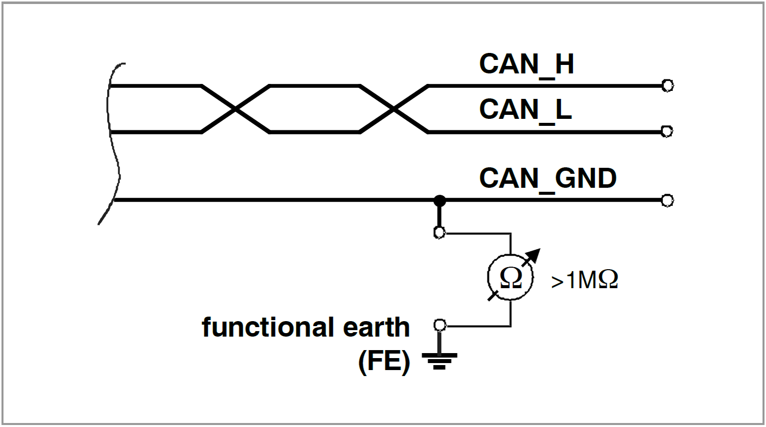
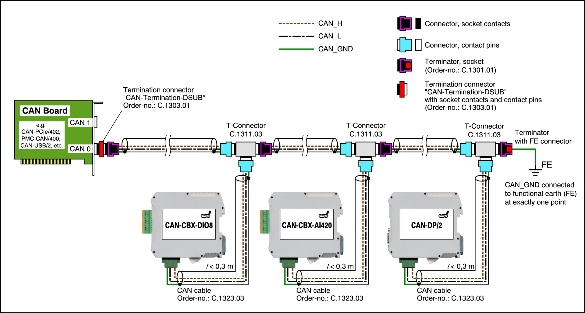
CAN_GND of the CAN network should be connected to the functional earth potential (FE) at only one point.
This test indicates whether the CAN_GND is grounded at one or more points.
Note: This test can only be performed with electrically isolated CAN nodes.
To test, please proceed as follows:
- Disconnect the CAN_GND from the earth potential (FE).
-
Measure the DC resistance between CAN_GND and earth potential (see circuit diagram ground measurement).
Expected result:
The measured resistance should be greater than a 1 MΩ. If it is smaller, please look for additional grounding of the CAN_GND wires.
After the test, do not forget to reconnect CAN_GND to the earth potential.
The correct Voltage Levels on CAN_H and CAN_L
Each node has a CAN transceiver that generates differential signals on the data lines. When network communication is idle, the CAN_H and CAN_L voltages are about 2.5 V to CAN_GND. Defective transceivers can change these quiescent voltages and interrupt network communication.
To test for defective transceivers, please proceed as follows:
- Switch on all supply voltages.
- Terminate all network communication.
- Measure the DC voltage between CAN_H and GND (measuring point (2), see circuit diagram of a CAN network).
- Measure the DC voltage between CAN_L and GND (measuring point (3), see circuit diagram of a CAN network).
Expected result:
The measured voltage should be between 2.0 V and 3.0 V.
Possible causes of error:
If the voltage is less than 2.0 V or greater than 3.0 V, it is possible that one or more nodes have defective transceivers. If the voltage is lower than 2.0 V, please check the connection of the CAN_H and CAN_L lines.
To find a node with a defective transceiver in a network, please check individually the resistances of the CAN transceivers of the nodes (see next section).
The correct Resistance of the CAN Transceivers
CAN transceivers have circuits that control CAN_H and CAN_L. Experience shows that electrical damage can increase the leakage current in these circuits.
To measure the leakage current through the CAN circuits, please use an ohmmeter and proceed as follows:
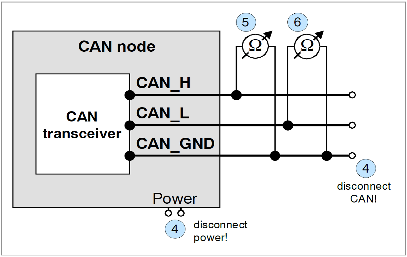
- Turn off the node (4) and disconnect it from the CAN network.
- Measure the DC resistance between CAN_H and CAN_GND,
measuring point (5). - Measure the DC resistance between CAN_L and CAN_GND,
measuring point (6).
For the position of node (4) and the measuring points (5) and (6), please refer to the diagram "Measurement of the input resistance".
Expected result:
The measured resistance should be greater than 10 kΩ for each measurement.
Possible causes of error:
If the resistance is significantly lower, the CAN transceiver may be defective.
Another indication of a faulty CAN transceiver is a very high deviation of the two measured input resistances (>> 200%).
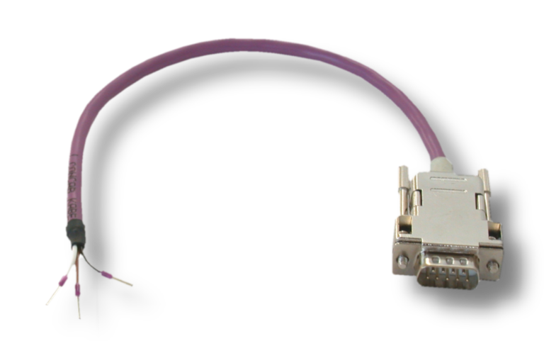
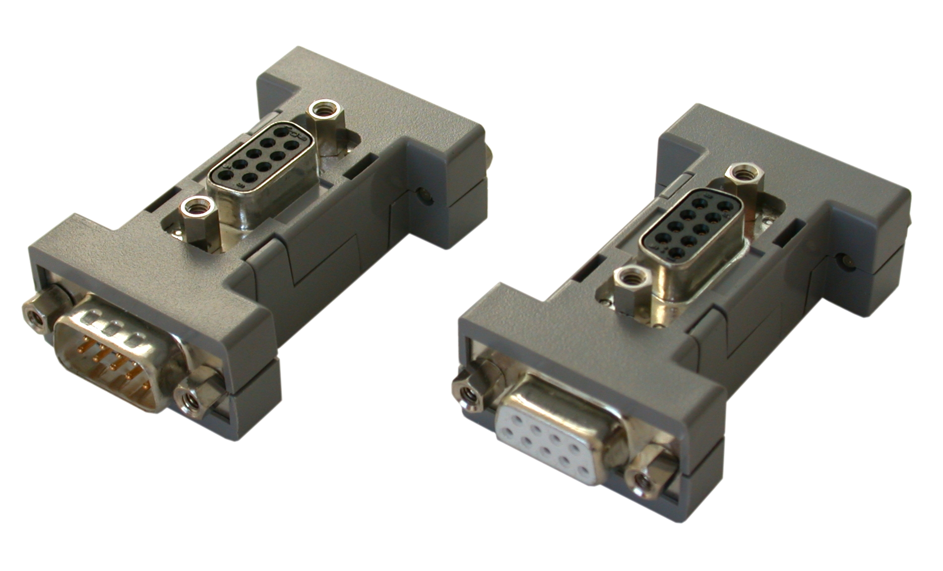
Please also have a look at our CAN cables and CAN accessories or read further information
Support at esd
If you cannot find a solution despite using the CAN bus troubleshooting guide, please contact our Technical Support.
You can also use our Support Form directly.

