Process IOs with wide Voltage Range
- 32 digital inputs with interrupt, 5 ... 30 VDC
-
32 digital outputs 6 ... 28 VDC/0.3 A
-
Counter: 4 inputs programmable as counters
Electrical Isolation and Circuit Protection
-
All I/Os electrically isolated
-
Outputs are sustained short-circuit-proof and support error detection with interrupt
-
Inputs are overvoltage protected between -3 VDC and +35 VDC
Pulse Processor HD63140
- All 32 outputs programmable for pulsewidth modulation (PWM) or gating control
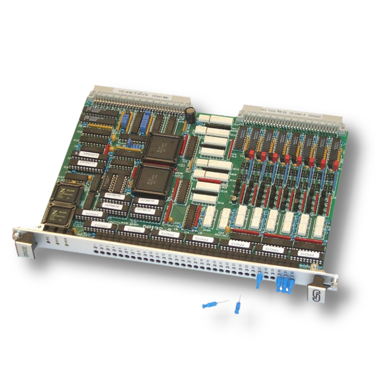
Optoisolated Process I/Os
VME-DPIO32 contains 32 optoisolated digital process I/O channels. It includes all necessary components on a VMEbus 6U board and needs one slot.
Wide Voltage Ranges
The 32 digital I/O channels are programmable in 8 groups of 4 channels as inputs or outputs. The 8 groups are electrically isolated from each other. The input channels accept an input voltage range of 5 VDC to 30 VDC. Each input channel can generate an interrupt on the VMEbus and that is programmable to rising or to falling edge. The inputs are overvoltage protected between -3 VDC and +35 VDC. The digital output channels accept an operating voltage range of 6 VDC to 24 VDC with a rated current of 0.3 A.
Output Protection and Error Signals
The outputs are driven by Quad High Side Drivers LMD18400. The protection circuit of the driver is activated by short-circuit, over temperature and overvoltage. An error signal will be generated by the drivers on the following conditions: no load, short circuit to GND, to VCC , overvoltage or over temperature of the driver module.
PWM
In addition to the bit programmable operating mode of the outputs, it is possible to use the single output channels via the pulse processor components HD63140 for pulse-width modulation (PWM). A total of 2 x 24 programmable 16 bit registers for switching period and resolution are available. The minimum pulse width amounts to 10 :s. The outputs can be synchronized.
Counter Inputs
Up to 4 digital inputs may be used as counter inputs at the CIO8536. The maximum counter frequency for the inputs is 3 MHz.
Display and Simulation
The actual I/O status and error status of each I/O channel is displayed by a two-coloured LED on the front panel of the VMEDPIO32.
Additionally, there are test sockets for each channel located on the front panel for stimulation of the input channels or for disable of the output driver error signal.
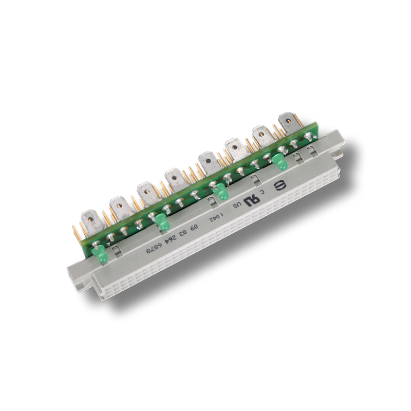
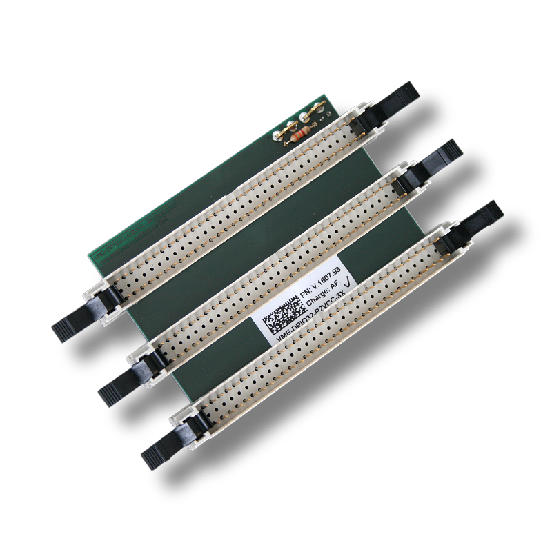
P2 Adapters support easy Wiring
The 64-pin adapter blocks VME-P2-ADAPT1 or VME-P2-ADAPT1 are connected via ribbon cable to the P2 connector of the VME-DPIO32/63140. They offer wiring with screw or clamp terminals for all P2 I/O signals. To feed power supply for the 8 output groups separately (4 outputs are combined to one group) the power adapter VMEDPIO32-P2VCC is used. If a separate wiring of the output groups is not necessary the adapter VME-DPIO32-P2VCC-3X feeds power to 3 VMEDPIO32/63160 installed in 3 VMEbus slots side-by-side is an economic solution.
Do you have special requirements regarding the product?
We are happy to provide you with a customer-specific option or adjustment to our products when purchasing appropiate quantities. Please contact our sales team for detailed information.

With the help of the button "Add to watchlist" you can save articles on your watchlist.
Afterwards, you can request your saved watch list as a quotation via a contact form.